Brake Disc Thickness And Runout
Brake discs (rotors) convert kinetic energy into heat through friction with pads. Thickness and lateral runout both influence heat capacity, pad contact pattern, and pedal feel. Thickness loss reduces thermal mass and can bring the rotor into a worn or out-of-spec condition. Runout describes how much the disc’s braking surface deviates from a true rotation axis, which can cause vibration, uneven pad wear, and squeal.
In practice, you measure thickness to compare against the manufacturer’s minimum specification and you measure runout to check for wobble. A common example: after a pad change, a steering-wheel shake at 60–90 km/h may point to runout or uneven pad transfer rather than pad material alone. Another example: a disc that measures near minimum thickness may still feel smooth if runout stays low, yet it can fail sooner under repeated hard stops.
Measurement quality matters because discs are rarely perfectly uniform. Even a good dial indicator setup can mislead if the disc is contaminated, the hub face is dirty, or the indicator tip is not aligned with the measurement direction. I’ve seen technicians chase a “bad rotor” that turned out to be a hub surface with old corrosion—annoying, because the disc itself looked fine on first glance.
How To Measure Thickness Correctly
Use The Right Points And Tool
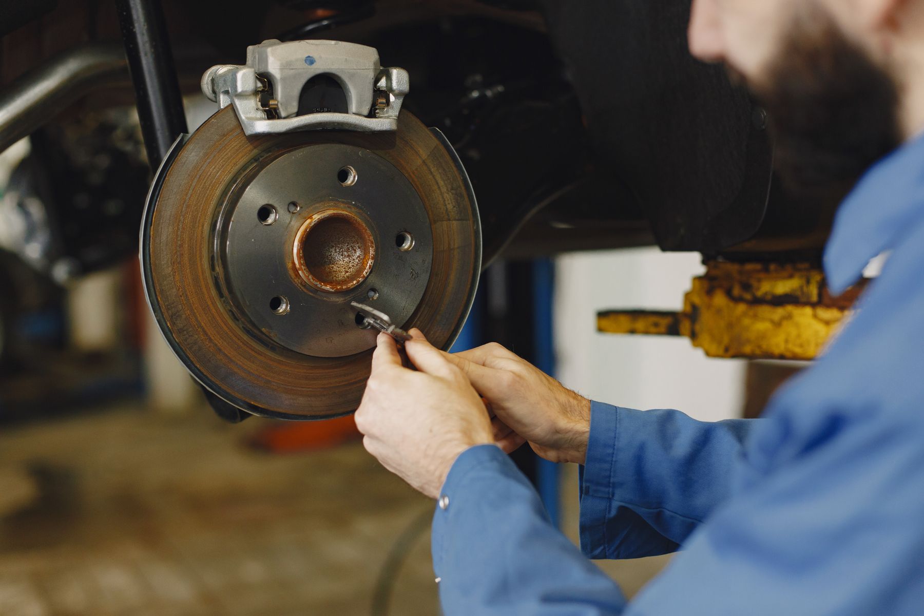
Measure disc thickness with a quality micrometer or a caliper designed for thin, flat surfaces. A micrometer often gives more repeatability because it contacts the rotor with a controlled spindle force. If you use a caliper, use the same jaw orientation each time and avoid measuring across chamfers or vent edges.
Take measurements at multiple locations across the braking surface, typically at two or more circumferential points and at two radii if the disc design allows. Many technicians measure at the thinnest visible area first, then confirm with additional points 90 degrees apart. If the disc has a known wear groove, measure just inside and just outside the groove so you can see the taper rather than a single “best guess.”
Record the minimum thickness you find, not the average. Service limits are based on minimum thickness at the thinnest point. If your readings vary by more than about 0.05 mm between repeated placements, stop and improve contact technique before interpreting the result.
Compare Against The Manufacturer Limit
Use the vehicle manufacturer’s published minimum thickness and discard thickness, not generic “rules of thumb.” Service limits vary by rotor design, vehicle weight, and brake system configuration. If you only have a parts catalog listing, look for a spec sheet or workshop manual excerpt that states the minimum thickness for that exact rotor part number.
When you compare, account for whether the rotor is solid or vented and whether the spec refers to the friction material thickness at the braking surface. Some rotors have a measurement method that avoids the outer chamfer; following that method reduces the chance of comparing apples to oranges.
If the rotor is below minimum thickness, replacement is the usual outcome. Resurfacing or machining may be restricted by design and by whether the rotor has a minimum remaining thickness after machining. Many modern rotors also have coatings or hardening layers that limit how much material can be removed.
Measure Runout And Interpret It
Set Up A Stable Dial Indicator
Measure lateral runout using a dial indicator with a magnetic base or a rigid mount. Clean the hub face and rotor mounting surfaces before measurement, because corrosion and debris can create a repeatable offset that disappears after cleaning. Rotate the disc by hand and confirm the indicator tip stays in contact without bouncing.
Place the indicator tip on the braking surface at a consistent radius. For many setups, measuring near the outer third of the braking surface gives a practical indicator of vibration risk, but follow the workshop manual if it specifies a radius. Keep the indicator stem aligned so the reading reflects lateral movement rather than a combination of lateral and radial error.
Zero the indicator, then rotate the disc slowly through at least one full revolution. Record the total indicated runout (TIR), which is the difference between the highest and lowest readings. A small aside from the garage: I’ve seen magnetic bases creep when the rotor surface is oily, and the runout number changes mid-rotation like it’s “breathing.” Wipe the mounting area and recheck zero if the base shifts.
Check Hub And Bearing Contributors
Runout can originate at the rotor, the hub face, or the wheel bearing. To separate causes, repeat the measurement after cleaning the hub face and after reinstalling the rotor with the same orientation. If runout changes significantly after cleaning, the interface was the dominant issue. If runout stays similar, the rotor or the bearing/hub assembly may be the limiting factor.
Also check wheel bearing play using the vehicle’s service procedure. A bearing with looseness can create a fluctuating axis, which shows up as runout even with a new rotor. In some cases, the rotor “passes” a runout check but the steering vibration persists because the bearing has a different failure mode under load.
Interpret runout against the vehicle’s spec. Many manufacturers publish a maximum allowable lateral runout in hundredths of a millimeter, but the threshold varies widely. If you cannot find a spec, treat the measurement as a diagnostic signal rather than a pass/fail verdict, and prioritize cleaning and reassembly checks before replacing parts.
Examples For Real-World Decisions
Example 1: Uneven Thickness After Pad Replacement
An anonymized driver replaces pads and notices a faint squeal after a week. Thickness measurements show the rotor’s minimum thickness is near the discard limit, with a visible wear groove. Runout measures low, suggesting the disc is not wobbling. The likely cause is uneven pad contact from the original wear pattern and possibly a caliper slide issue that prevented full pad sweep.
The next step is to inspect caliper slide lubrication and boot condition, then clean and verify pad fitment. After correcting caliper movement, the rotor may still require replacement due to minimum thickness, even if runout is acceptable. This scenario shows why thickness and runout must be interpreted together rather than treated as separate “checkboxes.”
Example 2: Steering Vibration With Acceptable Thickness
A different anonymized scenario involves steering-wheel vibration during braking at highway speeds. Rotor thickness remains above the minimum spec, but lateral runout reads high at the outer braking radius. Cleaning the hub face and reinstalling the rotor with the same orientation reduces runout, though it does not reach the lowest value seen on the first measurement.
The likely contributor is corrosion or debris at the disc-to-hub interface. The practical decision is to repeat runout measurement after thorough cleaning and correct torque, then reassess bearing play. If runout remains high after interface correction, rotor replacement becomes more defensible than resurfacing, since machining may not address the mounting interface problem.
Runout And Thickness
| Finding | What It Suggests | What To Do Next | Common Pitfall |
|---|---|---|---|
| Thickness near minimum | Rotor wear limits thermal margin | Measure multiple points; compare to spec; plan replacement if below minimum | Using one measurement spot and missing a groove |
| High runout, low thickness | Interface or bearing issue more likely than wear | Clean hub face; reinstall; remeasure; check bearing play | Assuming a new rotor fixes hub corrosion |
| High runout after cleaning | Rotor or hub/bearing assembly likely | Inspect rotor for damage; verify mounting; test bearing condition | Measuring at inconsistent radii or with a drifting indicator base |
| Low runout, thickness below spec | Thermal and wear limit reached | Replace rotor; inspect pads and caliper movement for why wear accelerated | Replacing rotor without checking caliper slide or pad fit |
Step-by-step checklist for a careful measurement session: clean hub face, mount rotor, torque wheel fasteners to spec, zero the dial indicator, measure TIR at a consistent radius, rotate through a full revolution, repeat after cleaning if runout looks suspicious, then measure thickness at multiple points and record the minimum. If your numbers change after reassembly, the interface is doing most of the work.
Mistakes That Skew Results
One frequent mistake is measuring thickness with the caliper jaws contacting the rotor’s chamfer or vent edge. That placement can under-report thickness by enough to make a rotor appear closer to minimum than it truly is. Another mistake is using a micrometer without cleaning the rotor surface; dust and rust pits change the contact point and add scatter.
Runout errors often come from indicator alignment. If the indicator tip is not perpendicular to the disc surface, the reading mixes lateral and radial motion. A magnetic base that isn’t tight enough can shift during rotation, and the dial needle will “walk” in a way that looks like wobble. I once saw a dial indicator reading change by about 0.03 mm simply because the base was resting on a curved casting surface rather than a flat bracket.
Reassembly mistakes also matter. If the wheel bolts or hub nut are tightened unevenly, the rotor can seat with a slight tilt. If you measure runout before the wheel is torqued to spec, the rotor may not be clamped the way it is during driving. That mismatch can lead to replacing parts based on a measurement that would improve after correct torque.
Finally, avoid assuming resurfacing fixes runout. Machining can reduce thickness unevenness, but it does not correct a rotor-to-hub mounting interface that creates lateral offset. If the hub face is uneven, a machined rotor can still wobble once clamped.
FAQ
What Thickness Measurement Points Should I Use?
Measure at multiple circumferential points and at the radii that correspond to the braking surface where wear is visible. Record the minimum thickness and compare it to the vehicle’s published minimum for that rotor part number.
How Do I Measure Lateral Runout Accurately?
Use a dial indicator with a rigid mount, zero it, and measure total indicated runout by rotating the disc one full revolution. Keep the indicator tip at a consistent radius on the braking surface and record the highest minus lowest reading.
Does High Runout Always Mean a Bad Rotor?
High runout can come from hub face corrosion, debris, rotor mounting mismatch, or wheel bearing play. Cleaning the hub face and repeating the measurement after reinstalling helps separate interface issues from rotor or bearing issues.
Can I Resurface a Rotor Instead Of Replacing It?
Resurfacing depends on the rotor design and whether it leaves enough thickness above the minimum after machining. Many manufacturers restrict machining and may not allow it for certain rotor types or coatings.
Why Do Measurements Change After Reinstalling the Rotor?
Rotor-to-hub contact can vary due to corrosion, paint, debris, or slight differences in rotor orientation. If runout improves after cleaning and correct torque, the interface was the dominant factor.
Author's Insight
Thickness and runout measurements are diagnostic signals, not guarantees of a single root cause. The most reliable workflow starts with correct mounting and hub cleaning, then measures thickness at multiple points and runout at a consistent radius. Workshop manuals remain the best source for minimum thickness and maximum allowable runout because values vary by rotor design and vehicle.
Measurement scatter often comes from technique: caliper placement across chamfers, dial indicator misalignment, and indicator base drift. A careful approach—repeat measurements and compare results after cleaning—reduces the chance of replacing parts based on a misleading reading.
If you cannot find published specs for your exact rotor part number, treat the numbers as relative indicators and focus on correcting interface and bearing contributors before concluding the rotor is defective.
Key Takeaways
- Measure thickness at multiple points and use the minimum reading against the manufacturer’s discard limit.
- Measure lateral runout with a dial indicator at a consistent radius and record total indicated runout.
- Clean the hub face and torque fasteners to spec before judging runout; interface issues can mimic a bad rotor.
- High runout can originate from hub/bearing problems, so check bearing play when runout stays high after cleaning.
- Resurfacing decisions depend on rotor design and remaining thickness after machining, not on runout alone.